Summary: Over 90% of the thousands of ABS units we receive every year at Sinspeed are removed because of a supposed “wheel speed sensor fault”. In reality, the majority of those sensors are perfectly healthy — the real problem lies inside the ABS pump/module (failed internal circuits, pressure sensors, or wiring inside the sealed unit) that cannot be diagnosed or fixed on the car.
This is the exact workshop-proven, 10-step diagnostic process our technicians use every day — complete with multimeter values, oscilloscope patterns, air-gap specs, and live-data checks — so you can rule out the sensor and wiring with 100% certainty before removing the ABS unit.
If you’ve cleaned the sensor, replaced it, checked the tone ring and wiring, and the ABS light is still on with a wheel speed sensor (WSS) fault (or the scope shows a perfect square wave but the module refuses to accept it), the fault is inside the ABS module itself. That’s when garages and owners across the UK send the unit to us — the country’s largest ABS remanufacturer. Explore our ABS repair services — fully rebuilt, upgraded, tested on vehicle rigs and backed by our unlimited-mileage lifetime warranty.
Important Safety Note
The information in this guide is intended for vehicle owners with basic mechanical knowledge and qualified technicians only. Working on braking systems can affect vehicle safety. If you are unsure at any stage, stop and consult a professional workshop. Sinspeed accepts no liability for improper repairs.
What This Guide Covers
Wheel speed sensors are the most critical input for ABS, traction control, stability control, hill-start assist, and even the speedometer on many vehicles. This page explains the fundamental operating principles of both passive and active wheel speed sensors, their differences, symptoms of failure, common causes, and the most detailed, workshop-proven diagnostic procedure available online using a multimeter and oscilloscope.
Table of Contents
- Why wheel speed sensors matter
- Passive vs active sensors – the key differences
- Symptoms of failure
- Most common causes of failure
- Full 10-step diagnostic process
- What to do when the sensor is NOT the problem
Why Wheel Speed Sensors Matter
Today’s vehicles rely heavily on electronic assistance systems to improve safety and comfort. The wheel speed sensor is the primary source of data for ABS, TCS, ESP, adaptive cruise control, and many transmission and navigation functions. The ABS control unit receives this data in real time and shares it across the CAN-bus network. A single faulty sensor can disable multiple safety systems and trigger warning lights — which is why it is the first thing every garage checks when an ABS light appears.
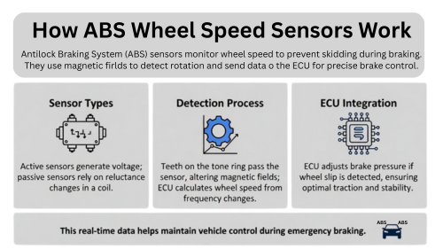
Passive vs Active Sensors – The Key Differences
Wheel speed sensors are divided into two main types:
| Type | Passive (Inductive) | Active (Hall / Magneto-resistive) |
|---|---|---|
| Power | None – self-generating | Requires 5–14 V supply from ABS module |
| Wires | 2 | 2 or 3 |
| Signal | Sine wave (AC voltage) | Digital square wave (PWM current) |
| Low-speed accuracy | Poor – cannot read below ~5 km/h | Excellent – reads from 0 km/h |
| Typical vehicles | Pre-1998 | 1998 onwards (99 % of cars on the road) |
| Air gap tolerance | Tight (0.4–1.2 mm) | Wide (0.5–2.0 mm) |
Symptoms of Failure
- ABS warning light on (constant or speed-dependent)
- Traction / stability control light illuminated
- Speedometer erratic, stuck, or reading zero
- Harsh automatic gear changes
- Brakes lock or pulse when they should not
- Light only appears above ~20 mph (classic tone-ring or gap issue)
Most Common Causes of Failure
- Physical damage / impact
- Corrosion or ferrous debris on the sensor tip
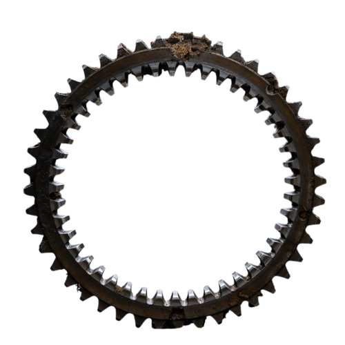
- Cracked or missing teeth on the tone / reluctor ring
- Chafed or broken wiring
- Excessive wheel-bearing play widening the air gap
- Water ingress into the connector or sensor
- Internal failure of the sensor electronics (active sensors)
At Sinspeed we receive thousands of ABS modules every year from garages across the UK. More than 90% of those cases started life as a wheel speed sensor problem. This is the most comprehensive, workshop-proven guide you will find anywhere — written for DIY owners who want to save money and for qualified technicians who need absolute certainty before removing the ABS unit.
1. Scan the Vehicle First – Never Skip This Step
Every modern car stores specific ABS fault codes that tell you exactly which wheel is affected and whether the problem is electrical, mechanical, or signal-related. Skipping the scan wastes hours chasing the wrong corner of the car.
Step 1 – Connect an OBD scanner capable of reading ABS codes
Read the codes, note which wheel is flagged, and check live data for wheel speeds. Write everything down.
2. Visual Inspection – 80% of Intermittent Faults Are Visible
Most wheel speed sensor problems are caused by physical damage, contamination, or wiring that has rubbed through. A careful 10-minute inspection under the car will reveal the majority of faults before you even pick up a meter.
Step 2 – Lift the car safely and remove the wheel if necessary
Examine the sensor head for cracks, rust, or metal shavings. Inspect the tone ring for missing teeth or cracks. Trace the harness for chafing against suspension components or heat shields.
3. Check the Air Gap and Mechanical Condition
The distance between the sensor tip and the tone ring is critical. Too wide and the signal becomes weak or disappears completely; excessive wheel-bearing play will vary the gap while driving and cause drop-outs.
Step 3 – Measure the air gap with a feeler gauge
Passive sensors: 0.4 – 1.2 mm
Active sensors: 0.5 – 2.0 mm
Check for bearing play by rocking the wheel top-to-bottom.
4. Clean First – The Free Fix That Works in 30 % of Cases
Road salt, brake dust, and water turn connectors green and coat sensor tips in ferrous debris. A two-minute clean often restores the signal completely.
Step 4 – Clean the sensor tip and tone ring with brake cleaner
Dry the connector thoroughly and reseat it firmly. Clear the fault codes and test drive to see if the fault persists. If it does, you could try swapping out the sensor to another wheel – if the fault travels to the other wheel, replace the sensor.
Not sure how to clear the fault codes? Check out our guide on how to reset an ABS light.
5. Passive Sensor Multimeter Tests (Pre-1998 Cars)
Passive sensors generate their own AC voltage as the tone ring passes. Resistance and output voltage checks are quick and conclusive.
Step 5 – Unplug the sensor and perform these two tests
- Resistance across the two pins: 800 – 2000 Ω (open or short = faulty)
- Spin the wheel by hand with multimeter on AC volts: minimum 0.2 V rising with speed (no voltage = bad sensor or huge gap).
6. Active Sensor Multimeter Tests (1998 Onwards)
Active sensors need power from the ABS module and output a digital current signal. Checking supply voltage and current draw instantly reveals dead sensors or wiring faults.
Step 6 – Ignition ON, back-probe the connector
- Voltage across the two pins (or supply pin on 3-wire): 8 – 14 V expected
- Current draw on signal wire (series measurement): should switch between ~7 mA and ~14 mA when wheel is spun No voltage or stuck current = wiring or module issue; stuck current only = dead sensor.
7. Oscilloscope Test – The One Test That Never Lies
A multimeter only shows averages; an oscilloscope shows the actual waveform shape, drop-outs, noise, and intermittents that no other tool can catch.
Step 7 – Connect the scope to the signal wire and road test
Good active sensor: clean square wave, sharp edges, frequency rises linearly with speed. Common failures you’ll see: flat line, missing pulses (tone ring), noisy trace (water/corrosion), or stuck high/low (dead ASIC).
8. Tone Ring Inspection Under Load
Some cracks or loose encoder rings only open when the wheel is under load or flexed, causing drop-outs that only appear while driving.
Step 8 – Spin the wheel while watching the scope
Look for drop-outs that appear only when the wheel is rocked or under suspension movement.
9. Full Wiring Continuity and Ground Test
Even a 0.5 Ω increase in resistance or a poor ground can make an active sensor appear dead. This step rules out the harness completely.
Step 9 – Using the wiring diagram, test continuity from sensor connector to ABS module pins
Check ground path to chassis and verify no voltage drop under load.
10. Final Road Test Verification
The only way to be 100 % certain is to confirm all four wheels read identical speeds under real driving conditions — acceleration, braking, and cornering.
Step 10 – Clear codes, road test with scanner connected
Watch live data: all four wheels must match perfectly. If they do and the light stays off — diagnosis complete.
Final Thoughts – When the Sensor Isn’t the Problem
If you’ve followed every step above — new sensor fitted, wiring perfect, tone ring spotless, scope pattern textbook — and the ABS light is still on, the fault has moved inside the ABS pump/module itself.
That’s the moment thousands of garages trust us with the unit every year.
At Sinspeed we specialise in remanufacturing these modules on vehicle-simulation test benches that replicate real road conditions (heat, vibration, hydraulic load). Every unit is stripped to board level, common design weaknesses are upgraded with higher-grade components, and the entire system is rigorously validated before it leaves.
The result? A fully plug-and-play module that drops straight back in — no coding, no pairing, no return visits — and is backed by our unlimited-mileage lifetime warranty.
So whether you’re a DIY owner who’s reached the limit of what can be done at home, or a busy workshop that needs a reliable, no-hassle fix for your customer — send the ABS unit to us. We’ll make it better than new and get it back to you fast.